Clasification Society Rules and Regulations - Rules and Regulations for the Classification of Offshore Units, January 2016 - Part 11 PRODUCTION, STORAGE AND OFFLOADING OF LIQUEFIED GASES IN BULK - Chapter 4 Cargo Containment - Section 4 Structural Integrity

Section 4 Structural Integrity
4.1 General
4.1.1 The structural design shall ensure that tanks have an adequate capacity to sustain all relevant loads with an adequate margin of safety. This should take into account the possibility of plastic deformation, buckling, fatigue and loss of liquid and gas tightness.
4.1.2 The structural integrity of cargo containment systems can be demonstrated by compliance with Pt 11, Ch 4, 6.1 Type A independent tanks to 4.26, as appropriate for the cargo containment system type.
4.1.3 The structural integrity of cargo containment system types that are of novel design and differ significantly from those covered by Pt 11, Ch 4, 6.1 Type A independent tanks to 4.26 shall be demonstrated by compliance with Pt 11, Ch 4, 8.1 Design for novel concepts to ensure that the overall level of safety provided in this chapter is maintained.
4.2 Structural analyses
4.2.1 Analysis
The design analyses shall be based on accepted principles of statics, dynamics and strength of materials.
Simplified methods or simplified analyses may be used to calculate the load effects, provided that they are conservative. Model tests may be used in combination with, or instead of, theoretical calculations. In cases where theoretical methods are inadequate, model or full-scale tests may be required.
When determining responses to dynamic loads, the dynamic effect shall be taken into account where it may affect structural integrity.
Where direct calculation procedures are adopted, the assumptions made and other details of the calculations are to be submitted.
4.2.2 Load scenarios
For each location or part of the cargo containment system to be considered and for each possible mode of failure to be analysed, all relevant combinations of loads that may act simultaneously shall be considered.
The most onerous load scenarios for all relevant phases of the life-cycle shall be considered. Loads during construction/handling, installation, on-site operation, inspection/maintenance including testing and in transit/disconnect conditions shall be considered, as applicable.
4.2.3 When the static and dynamic stresses are calculated separately and unless other methods of calculation are justified, the total stresses shall be calculated according to:


where:
σx.st, σy.st, σz.st, τxy.st, τxz.st and τyz.st = static stresses
σx.dyn, σy.dyn, σz.dyn, τxy.dyn, τxz.dyn and τyz.dyn = dynamic stresses
Each shall be determined separately from acceleration components and hull strain components due to deflection and torsion.
4.3 Design conditions
4.3.1 All relevant failure modes shall be considered in the design for all relevant load scenarios and design conditions. The design conditions are given in the earlier part of this Chapter, and the load scenarios are covered by Pt 11, Ch 4, 4.2 Structural analyses 4.2.2.
4.3.2 On-site operation design condition
- Plastic deformation and buckling shall be considered.
- Analysis shall be based on characteristic load values as follows:
Permanent Loads Expected Values Functional Loads Specified Values Environmental Loads Wave loads are to be calculated at a return period of 100 years. - For the purpose of strength assessment the
following material parameters apply:
-
R
e = specified minimum yield stress at room temperature
(N/mm2). If the stress-strain curve does not show a defined
yield stress, the 0,2 per cent proof stress applies.
R m = specified minimum tensile strength at room temperature (N/mm2).
NOTE
For welded connections where under-matched welds, i.e. where the weld metal has lower tensile strength than the parent metal, are unavoidable, such as in some aluminium alloys, the respective R e and R m of the welds, after any applied heat treatment, shall be used. In such cases the transverse weld tensile strength shall not be less than the actual yield strength of the parent metal. If this cannot be achieved, welded structures made from such materials shall not be incorporated in cargo containment systems.
- The above properties shall correspond to the minimum specified mechanical properties of the material, including the weld metal in the as-fabricated condition. Subject to special consideration by LR, account may be taken of the enhanced yield stress and tensile strength at low temperature.
-
R
e = specified minimum yield stress at room temperature
(N/mm2). If the stress-strain curve does not show a defined
yield stress, the 0,2 per cent proof stress applies.
- The equivalent stress σc (von Mises, Huber)
shall be determined by:

where
σx = total normal stress in x-direction
σy = total normal stress in y-direction
σz = total normal stress in z-direction
τxy = total shear stress in x-y plane.
τxz = total shear stress in x-z plane
τyz = total shear stress in y-z plane.
- Allowable stresses for materials other than those covered by Chapter 6 shall
be subject to approval by LR in each case.
Details of the proposals are to be submitted for consideration.
- Stresses may be further limited by fatigue analysis, crack propagation
analysis and buckling criteria.
The stresses resulting from the 10 000 year return period wave loading are not to exceed yield, or a higher stress level, provided permanent deformation can be permitted.
- The fatigue design condition is the design condition with respect to accumulated cyclic loading.
- The maximum allowable cumulative fatigue damage ratio CW is to be
less than or equal to 0,5, but is to be no greater than 0,33 for any parts of
the supporting structure which are not accessible for inspection during the
service life of the unit.
The fatigue damage shall be based on the design life of the containment system but not less than 25 years unless agreed otherwise by LR.
- The fatigue assessment of the cargo containment system is to be verified in
accordance with the ShipRight Procedure for Ship Units.
The loading/unloading history is to be consistent with the intended operation of the ship unit. Plastic strain is to be accounted for in the low cycle region. Loading and unloading cycles are to include a complete pressure and thermal cycle.
- Design S-N curves used in the analysis shall be applicable to the
materials and weldments, construction details, fabrication procedures and
applicable state of the stress envisioned.
The S-N curves shall be based on a 97,6 per cent probability of survival corresponding to the mean minus two standard deviation curves of relevant experimental data up to final failure. Use of S-N curves derived in a different way requires adjustments to the acceptable C w values specified in Pt 11, Ch 4, 4.3 Design conditions 4.3.3 to Pt 11, Ch 4, 4.3 Design conditions 4.3.3.
- Analysis shall be based on characteristic load values as follows:
Permanent Loads Expected Values Functional Loads Specified values or specified history Environmental Loads Expected load history, but not less than 108 cycles If simplified dynamic loading spectra are used for the estimation of the fatigue life, those shall be specially considered by LR.
- Where the size of the secondary barrier is
reduced, as is provided for in Pt 11, Ch 4, 2.2 Cargo containment safety principles 2.2.3, fracture mechanics analyses
of fatigue crack growth shall be carried out for the primary barrier to
determine:
- Crack propagation paths in the structure.
- Crack growth rate.
- The time required for a crack to propagate to cause a leakage from the tank.
- The size and shape of through thickness cracks.
- The time required for detectable cracks to reach a critical state.
The fracture mechanics are in general based on crack growth data taken as a mean value plus two standard deviations of the test data.- In analysing crack propagation the largest initial crack or equivalent defect not detectable by the inspection method applied shall be assumed, taking into account the allowable non-destructive testing and visual inspection criterion as applicable.
- For the crack propagation analysis under the condition specified in Pt 11, Ch 4, 4.3 Design conditions 4.3.3, the simplified load distribution and sequence over the RD, as specified in Pt 11, Ch 4, 1.1 Definitions 1.1.9, may be used, unless different project-specific requirements apply. Project-specific requirements are to be submitted for consideration. Such distributions may be obtained as indicated in Pt 11, Ch 4, 4.3 Design conditions 4.3.3. Load distribution and sequence for longer periods, such as in Pt 11, Ch 4, 4.3 Design conditions 4.3.3 and Pt 11, Ch 4, 4.3 Design conditions 4.3.3 shall be approved by LR.
- The arrangements shall comply with Pt 11, Ch 4, 4.3 Design conditions 4.3.3 to Pt 11, Ch 4, 4.3 Design conditions 4.3.3 as applicable:
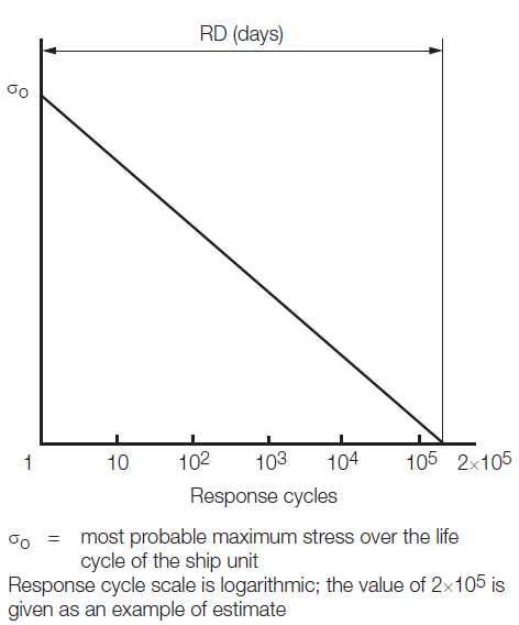
Figure 4.4.1 Simplified load distribution
- For failures that can be reliably detected by
means of leakage detection;
- C w shall be less than or equal to 0,5.
- The predicted remaining failure development time, from the point of detection of leakage until reaching a critical state, shall not be less than the RD, as specified in LR 4.1.1, unless different project-specific requirements apply. Project-specific requirements are to be submitted for consideration.
- For failures that cannot be detected by
leakage but that can be reliably detected at the time of in-service
inspections;
- C w shall be less than or equal to 0,5.
- Predicted remaining failure development time, from the largest crack not detectable by in-service inspection methods until reaching a critical state, shall not be less than three times the inspection interval.
- In particular locations of the tank where
effective defect or crack development detection cannot be assured, the
following, more stringent, fatigue acceptance criteria should be applied as a
minimum;
- C w shall be less than or equal to 0,1.
- The predicted failure development time, from the assumed initial defect until reaching a critical state, shall not be less than three times the lifetime of the tank.
4.3.4 Accident design condition
The accident design condition is a design condition for accidental loads with extremely low probability of occurrence. Analysis shall be based on the characteristic values as follows:
| Permanent Loads | Expected Values |
| Functional Loads | Specified values |
| Environmental Loads | Specified values |
| Accidental loads | Specified values or expected values |
Loads mentioned in Pt 11, Ch 4, 3.3 Functional loads 3.3.9 and Pt 11, Ch 4, 3.5 Accidental loads need not be combined with each other or with wave induced loads.
| Copyright 2016 Clasification Society, International Maritime Organization, International Labour Organization or Maritime and Coastguard Agency. All rights reserved. Clasification Society, its affiliates and subsidiaries and their respective officers, employees or agents are, individually and collectively, referred to in this clause as 'Clasification Society'. Clasification Society Register assumes no responsibility and shall not be liable to any person for any loss, damage or expense caused by reliance on the information or advice in this document or howsoever provided, unless that person has signed a contract with the relevant Clasification Society entity for the provision of this information or advice and in that case any responsibility or liability is exclusively on the terms and conditions set out in that contract. |  |