A.II Fire Dampers
Clasification Society 2024 - Version 9.40
Statutory Documents - IMO Publications and Documents - Resolutions - Assembly - IMO Resolution A.754(18) – Recommendation on Fire Resistance Tests for “A”, “B” and “F” Class Divisions – (Adopted on 4 November 1993) - Annex - Recommendation on Fire Resistance Tests for “A”, “B” and “F” Class Divisions1 - Appendix - Testing of Windows, Fire Dampers, Pipe Penetrations and Cable Transits - A.II Fire Dampers

A.II Fire Dampers

1 General

 "A" class divisions may have to be pierced for the passage of ventilation ducting, and arrangements should be made to ensure that the effectiveness of the division in relation to the criterion for integrity, as specified in 9.2 of the recommendation, is not impaired. Provisions should also be made to ensure that, should a fire be initiated within, or gain access to, ventilation ductwork, such a fire does not pass through the division within the ductwork.

 To provide for both these requirements, fire dampers are provided within or fixed to spigots or coamings which are welded to the structural core and are insulated to the same standard as the division.

2 Nature of test specimens

2.1 Dimensions

 The maximum and minimum sizes (in terms of both the width and the height, or the diameter) of each type of fire damper for which approval is sought should be tested in both vertical and horizontal orientation.

2.2 Design

  2.2.1 A bulkhead which includes the damper should be constructed in accordance with 2.1.1 of the recommendation and should be insulated to class A-60 on the stiffened face, which should be the face which is not exposed to the heating conditions of the test. A deck which includes the damper should be constructed in accordance with 2.2.1 of the recommendation and should be insulated to class A-60 on the stiffened face, which should be the face which is exposed to the heating conditions of the test.

  2.2.2 Fire dampers should be incorporated into or fixed to coamings or spigots, which should be welded or bolted into the structural core. The coaming or spigot including the damper should have a length of 900 mm (450 mm on each side of the structural core) and a thickness as follows:

Widthfootnote or diameter of the duct Minimum thickness of coaming or spigot
Up to and including 300 mm 3 mm
760 mm and over 5 mm

 For widths or diameters of ducts in excess of 300 mm but less than 760 mm, the thickness of the coaming or spigot should be obtained by interpolation.

 The coaming or spigot should be insulated as shown in Figure A1.

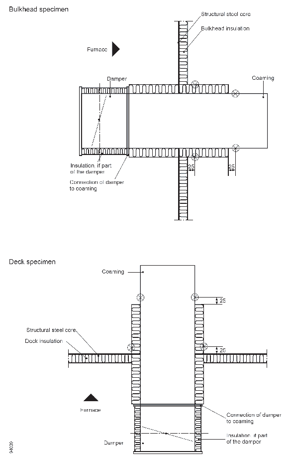
Figure A1 Fire dampers: insulation on test specimens and position of unexposed-face - thermocouples

  2.2.3 The coamings or spigots (including insulation) should be positioned only in the top half of a bulkhead but should be no closer than 200 mm from the edges of a bulkhead or a deck. Where more than one damper is to be tested simultaneously in a division, the separation between adjacent coamings or spigots (including insulation) should not be less than 200 mm. When more than one damper is included in a bulkhead, the top edges of all dampers should be, as far as possible, at the same height.

  2.2.4 The fire dampers should be positioned on the exposed face of the bulkhead or deck, at a distance of at least 225 mm from the structural core, with their operative controls also on that side of the division.

  2.2.5 Fire dampers which are operated automatically should be in the open position at the start of the test.

3 Instrumentation

3.1 Positioning of thermocouples on the specimen

 For each fire damper, two thermocouples should be fixed to the unexposed face at each of the following locations:

  • on the surface of the insulation provided to the coaming or spigot at a distance of 25 mm from the unexposed surface of the division; and
  • on the surface of the coaming or spigot at a distance of 25 mm from where the coaming or spigot emerges from its insulation.

 For fire dampers in bulkheads, for each of the positions indicated above, one of the thermocouples should be fixed on the top surface of the coaming or spigot and the other thermocouple should be fixed on the bottom surface of the coaming or spigot.

4 Method of Test

 It will not always be possible to utilize the cotton-wool-pad test to evaluate the integrity of a fire damper since radiation through the damper could be sufficient to cause ignition of the cotton-wool pad. In such cases, cracks or openings in fire dampers should not be such as to allow the gap gauges to enter in the manner described in 8.4.4 of the recommendation.

 The performance of fire dampers may be related to their ability to satisfy both the insulation and the integrity criteria or may be related only to the requirements for integrity, depending on the requirements of the Administration.


Copyright 2022 Clasifications Register Group Limited, International Maritime Organization, International Labour Organization or Maritime and Coastguard Agency. All rights reserved. Clasifications Register Group Limited, its affiliates and subsidiaries and their respective officers, employees or agents are, individually and collectively, referred to in this clause as 'Clasifications Register'. Clasifications Register assumes no responsibility and shall not be liable to any person for any loss, damage or expense caused by reliance on the information or advice in this document or howsoever provided, unless that person has signed a contract with the relevant Clasifications Register entity for the provision of this information or advice and in that case any responsibility or liability is exclusively on the terms and conditions set out in that contract.