6.1 Goal
The goal of this chapter is to provide that gas storage is adequate so as to minimize
the risk to personnel, the ship and the environment to a level that is equivalent to
a conventional oil fuelled ship.
6.2 Functional requirements
This chapter relates to functional requirements in 3.2.1, 3.2.2, 3.2.5
and 3.2.8 to 3.2.17. In particular the following apply:
-
.1 the fuel containment system shall be so designed that a leak from the tank
or its connections does not endanger the ship, persons on board or the
environment. Potential dangers to be avoided include:
-
.1 exposure of ship materials to temperatures below acceptable
limits;
-
.2 flammable fuels spreading to locations with ignition sources;
-
.3 toxicity potential and risk of oxygen deficiency due to fuels and
inert gases;
-
.4 restriction of access to muster stations, escape routes and
life-saving appliances (LSA); and
-
.5 reduction in availability of LSA.
-
.2 the pressure and temperature in the fuel tank shall be kept within the
design limits of the containment system and possible carriage requirements
of the fuel;
-
.3 the fuel containment arrangement shall be so designed that safety actions
after any gas leakage do not lead to an unacceptable loss of power; and
-
.4 if portable tanks are used for fuel storage, the design of the fuel
containment system shall be equivalent to permanent installed tanks as
described in this chapter.
6.3 Regulations – General
6.3.1 Natural gas in a liquid state may be stored with a maximum
allowable relief valve setting (MARVS) of up to 1.0 MPa.
6.3.2 The Maximum Allowable Working Pressure (MAWP) of the gas fuel tank
shall not exceed 90% of the Maximum Allowable Relief Valve Setting (MARVS).
6.3.3 A fuel containment system located below deck shall be gas tight
towards adjacent spaces.
6.3.4 All tank connections, fittings, flanges and tank valves must be
enclosed in gas tight tank connection spaces, unless the tank connections are on
open deck. The space shall be able to safely contain leakage from the tank in case
of leakage from the tank connections.
6.3.5 Pipe connections to the fuel storage tank shall be mounted above
the highest liquid level in the tanks, except for fuel storage tanks of type C.
Connections below the highest liquid level may however also be accepted for other
tank types after special consideration by the Administration.
6.3.6 Piping between the tank and the first valve which release liquid in
case of pipe failure shall have equivalent safety as the type C tank, with dynamic
stress not exceeding the values given in 6.4.15.3.1.2.
6.3.7 The material of the bulkheads of the tank connection space shall
have a design temperature corresponding with the lowest temperature it can be
subject to in a probable maximum leakage scenario. The tank connection space shall
be designed to withstand the maximum pressure build up during such a leakage.
Alternatively, pressure relief venting to a safe location (mast) can be
provided.
6.3.8 The probable maximum leakage into the tank connection space shall
be determined based on detail design, detection and shutdown systems.
6.3.9 If piping is connected below the liquid level of
the tank it has to be protected by a secondary barrier up to the first valve.
6.3.10 If liquefied gas fuel storage tanks are
located on open deck the ship steel shall be protected from potential leakages from
tank connections and other sources of leakage by use of drip trays. The material is
to have a design temperature corresponding to the temperature of the fuel carried at
atmospheric pressure. The normal operation pressure of the tanks shall be taken into
consideration for protecting the steel structure of the ship.
6.3.11 Means shall be provided whereby liquefied gas
in the storage tanks can be safely emptied.
6.3.12 It shall be possible to empty, purge and vent
fuel storage tanks with fuel piping systems. Instructions for carrying out these
procedures must be available on board. Inerting shall be performed with an inert gas
prior to venting with dry air to avoid an explosion hazardous atmosphere in tanks
and fuel pipes. See detailed regulations in 6.10.
6.4 Regulations for liquefied gas
fuel containment
6.4.1 General
6.4.1.1 The risk assessment required in 4.2 shall include evaluation of
the ship's liquefied gas fuel containment system, and may lead to additional safety
measures for integration into the overall vessel design.
6.4.1.2 The design life of fixed liquefied gas fuel containment system
shall not be less than the design life of the ship or 20 years, whichever is
greater.
6.4.1.3 The design life of portable tanks shall not be less than 20
years.
6.4.1.4 Liquefied gas fuel containment systems shall be designed in
accordance with North Atlantic environmental conditions and relevant long-term sea
state scatter diagrams for unrestricted navigation. Less demanding environmental
conditions, consistent with the expected usage, may be accepted by the
Administration for liquefied gas fuel containment systems used exclusively for
restricted navigation. More demanding environmental conditions may be required for
liquefied gas fuel containment systems operated in conditions more severe than the
North Atlantic environment. footnote,footnote
6.4.1.5 Liquefied gas fuel containment systems shall be designed with
suitable safety margins:
- .1 to withstand, in the intact condition, the environmental
conditions anticipated for the liquefied gas fuel containment system's
design life and the loading conditions appropriate for them, which shall
include full homogeneous and partial load conditions and partial filling to
any intermediate levels; and
- .2 being appropriate for uncertainties in loads, structural
modelling, fatigue, corrosion, thermal effects, material variability, aging
and construction tolerances.
6.4.1.6 The liquefied gas fuel containment system structural strength
shall be assessed against failure modes, including but not limited to plastic
deformation, buckling and fatigue. The specific design conditions that shall be
considered for the design of each liquefied gas fuel containment system are given in
6.4.15. There are three main categories of design conditions:
-
.1 Ultimate Design Conditions – The liquefied gas fuel containment system
structure and its structural components shall withstand loads liable to
occur during its construction, testing and anticipated use in service,
without loss of structural integrity. The design shall take into account
proper combinations of the following loads:
-
.1 internal pressure;
-
.2 external pressure;
-
.3 dynamic loads due to the motion of the ship in all loading
conditions;
-
.4 thermal loads;
-
.5 sloshing loads;
-
.6 loads corresponding to ship deflections;
-
.7 tank and liquefied gas fuel weight with the corresponding reaction
in way of supports;
-
.8 insulation weight;
-
.9 loads in way of towers and other attachments; and
-
.10 test loads.
-
.2 Fatigue Design Conditions – The liquefied gas fuel containment system
structure and its structural components shall not fail under accumulated
cyclic loading.
- .3 Accidental Design Conditions – The liquefied gas fuel containment
system shall meet each of the following accident design conditions (accidental
or abnormal events), addressed in this Code:
-
.1 Collision – The liquefied gas fuel containment system shall
withstand the collision loads specified in 6.4.9.5.1 without
deformation of the supports or the tank structure in way of the
supports likely to endanger the tank and its supporting
structure.
-
.2 Fire – The liquefied gas fuel containment systems shall sustain
without rupture the rise in internal pressure specified in 6.7.3.1
under the fire scenarios envisaged therein.
-
.3 Flooded compartment causing buoyancy on tank – the anti-flotation
arrangements shall sustain the upward force, specified in 6.4.9.5.2
and there shall be no endangering plastic deformation to the hull.
Plastic deformation may occur in the fuel containment system
provided it does not endanger the safe evacuation of the ship.
6.4.1.7 Measures shall be applied to ensure that scantlings required
meet the structural strength provisions and are maintained throughout the design
life. Measures may include, but are not limited to, material selection, coatings,
corrosion additions, cathodic protection and inerting.
6.4.1.8 An inspection/survey plan for the liquefied gas fuel containment
system shall be developed and approved by the Administration. The inspection/survey
plan shall identify aspects to be examined and/or validated during surveys
throughout the liquefied gas fuel containment system's life and, in particular, any
necessary in-service survey, maintenance and testing that was assumed when selecting
liquefied gas fuel containment system design parameters. The inspection/survey plan
may include specific critical locations as per 6.4.12.2.8 or 6.4.12.2.9.
6.4.1.9 Liquefied gas fuel containment systems shall be designed,
constructed and equipped to provide adequate means of access to areas that need
inspection as specified in the inspection/survey plan. Liquefied gas fuel
containment systems, including all associated internal equipment shall be designed
and built to ensure safety during operations, inspection and maintenance.
6.4.2 Liquefied gas fuel containment safety principles
6.4.2.1 The containment systems shall be provided with a complete
secondary liquid-tight barrier capable of safely containing all potential leakages
through the primary barrier and, in conjunction with the thermal insulation system,
of preventing lowering of the temperature of the ship structure to an unsafe
level.
6.4.2.2 The size and configuration or arrangement of the secondary
barrier may be reduced or omitted where an equivalent level of safety can be
demonstrated in accordance with 6.4.2.3 to 6.4.2.5 as applicable.
6.4.2.3 Liquefied gas fuel containment systems for which the probability
for structural failures to develop into a critical state has been determined to be
extremely low but where the possibility of leakages through the primary barrier
cannot be excluded, shall be equipped with a partial secondary barrier and small
leak protection system capable of safely handling and disposing of the leakages (a
critical state means that the crack develops into unstable condition).
The arrangements shall comply with the following:
- .1 failure developments that can be reliably detected before
reaching a critical state (e.g. by gas detection or inspection) shall have a
sufficiently long development time for remedial actions to be taken;
and
- .2 failure developments that cannot be safely detected before
reaching a critical state shall have a predicted development time that is
much longer than the expected lifetime of the tank.
6.4.2.4 No secondary barrier is required for liquefied gas fuel
containment systems, e.g. type C independent tanks, where the probability for
structural failures and leakages through the primary barrier is extremely low and
can be neglected.
6.4.2.5 For independent tanks requiring full or partial secondary barrier,
means for safely disposing of leakages from the tank shall be arranged.
6.4.3 Secondary barriers in relation to tank types
Secondary barriers in relation to the tank types defined in 6.4.15 shall
be provided in accordance with the following table.
| Basic tank type
|
Secondary barrier requirements
|
| Membrane
|
Complete secondary barrier
|
|
|
|
| Independent
|
|
| Type A
|
Complete secondary barrier
|
| Type B
|
Partial secondary barrier
|
| Type C
|
No secondary barrier required
|
6.4.4 Design of secondary barriers
The design of the secondary barrier, including spray shield if fitted,
shall be such that:
-
.1 it is capable of containing any envisaged leakage of liquefied gas fuel
for a period of 15 days unless different criteria apply for particular
voyages, taking into account the load spectrum referred to in
6.4.12.2.6;
-
.2 physical, mechanical or operational events within the liquefied gas fuel
tank that could cause failure of the primary barrier shall not impair the
due function of the secondary barrier, or vice versa;
-
.3 failure of a support or an attachment to the hull structure will not lead
to loss of liquid tightness of both the primary and secondary barriers;
-
.4 it is capable of being periodically checked for its effectiveness by means
of a visual inspection or other suitable means acceptable to the
Administration;
- .
5 the methods required in 6.4.4.4 shall be approved by the
Administration and shall include, as a minimum:
-
.1 details on the size of defect acceptable and the location within
the secondary barrier, before its liquid tight effectiveness is
compromised;
-
.2 accuracy and range of values of the proposed method for detecting
defects in .1 above;
-
.3 scaling factors to be used in determining the acceptance criteria
if full-scale model testing is not undertaken; and
-
.4 effects of thermal and mechanical cyclic loading on the
effectiveness of the proposed test.
-
.6 the secondary barrier shall fulfil its functional requirements at a static
angle of heel of 30°.
6.4.5 Partial secondary barriers and primary barrier small leak
protection system
6.4.5.1 Partial secondary barriers as permitted in 6.4.2.3 shall be used
with a small leak protection system and meet all the regulations in 6.4.4.
The small leak protection system shall include means to detect a leak in
the primary barrier, provision such as a spray shield to deflect any liquefied gas
fuel down into the partial secondary barrier, and means to dispose of the liquid,
which may be by natural evaporation.
6.4.5.2 The capacity of the partial secondary barrier shall be
determined, based on the liquefied gas fuel leakage corresponding to the extent of
failure resulting from the load spectrum referred to in 6.4.12.2.6, after the
initial detection of a primary leak. Due account may be taken of liquid evaporation,
rate of leakage, pumping capacity and other relevant factors.
6.4.5.3 The required liquid leakage detection may be by means of liquid
sensors, or by an effective use of pressure, temperature or gas detection systems,
or any combination thereof.
6.4.5.4 For independent tanks for which the geometry does not present
obvious locations for leakage to collect, the partial secondary barrier shall also
fulfil its functional requirements at a nominal static angle of trim.
6.4.6 Supporting arrangements
6.4.6.1 The liquefied gas fuel tanks shall be supported by the hull in a
manner that prevents bodily movement of the tank under the static and dynamic loads
defined in 6.4.9.2 to 6.4.9.5, where applicable, while allowing contraction and
expansion of the tank under temperature variations and hull deflections without
undue stressing of the tank and the hull.
6.4.6.2 Anti-flotation arrangements shall be provided for independent
tanks and capable of withstanding the loads defined in 6.4.9.5.2 without plastic
deformation likely to endanger the hull structure.
6.4.6.3 Supports and supporting arrangements shall withstand the loads
defined in 6.4.9.3.3.8 and 6.4.9.5, but these loads need not be combined with each
other or with wave-induced loads.
6.4.7 Associated structure and equipment
6.4.7.1 Liquefied gas fuel containment systems shall be designed for the
loads imposed by associated structure and equipment. This includes pump towers,
liquefied gas fuel domes, liquefied gas fuel pumps and piping, stripping pumps and
piping, nitrogen piping, access hatches, ladders, piping penetrations, liquid level
gauges, independent level alarm gauges, spray nozzles, and instrumentation systems
(such as pressure, temperature and strain gauges).
6.4.8 Thermal insulation
6.4.8.1 Thermal insulation shall be provided as required to protect the
hull from temperatures below those allowable (see 6.4.13.1.1) and limit the heat
flux into the tank to the levels that can be maintained by the pressure and
temperature control system applied in 6.9.
6.4.9 Design loads
6.4.9.1 General
6.4.9.1.1 This section defines the design loads that shall be considered
with regard to regulations in 6.4.10 to 6.4.12. This includes load categories
(permanent, functional, environmental and accidental) and the description of the
loads.
6.4.9.1.2 The extent to which these loads shall be considered depends on
the type of tank, and is more fully detailed in the following paragraphs.
6.4.9.1.3 Tanks, together with their supporting structure and other
fixtures, shall be designed taking into account relevant combinations of the loads
described below.
6.4.9.2 Permanent loads
6.4.9.2.1 Gravity loads
The weight of tank, thermal insulation, loads caused by towers and other
attachments shall be considered.
6.4.9.2.2 Permanent external loads
Gravity loads of structures and equipment acting externally on the tank
shall be considered.
6.4.9.3 Functional loads
6.4.9.3.1 Loads arising from the operational use of the tank system
shall be classified as functional loads.
6.4.9.3.2 All functional loads that are essential for ensuring the
integrity of the tank system, during all design conditions, shall be considered.
6.4.9.3.3 As a minimum, the effects from the following criteria, as
applicable, shall be considered when establishing functional loads:
- (a) internal pressure
- (b) external pressure
- (c) thermally induced loads
- (d) vibration
- (e) interaction loads
- (f) loads associated with construction and installation
- (g) test loads
- (h) static heel loads
- (i) weight of liquefied gas fuel
- (j) sloshing
- (k) wind impact, wave impacts and green sea effect for tanks
installed on open deck.
6.4.9.3.3.1 Internal pressure
- .1 In all cases, including 6.4.9.3.3.1.2, P0 shall not
be less than MARVS.
- .2 For liquefied gas fuel tanks where there is no temperature
control and where the pressure of the liquefied gas fuel is dictated only by the
ambient temperature, P0 shall not be less than the gauge vapour
pressure of the liquefied gas fuel at a temperature of 45°C except as
follows:
- .1 Lower values of ambient temperature may be accepted by
the Administration for ships operating in restricted areas. Conversely,
higher values of ambient temperature may be required.
- .2 For ships on voyages of restricted duration,
P0 may be calculated based on the actual pressure
rise during the voyage and account may be taken of any thermal
insulation of the tank.
- .3 Subject to special consideration by the Administration and to the
limitations given in 6.4.15 for the various tank types, a vapour pressure
Ph higher than P0 may be accepted for site
specific conditions (harbour or other locations), where dynamic loads are
reduced.
- .4 Pressure used for determining the internal pressure shall be:
- .1 (Pgd)max is the associated
liquid pressure determined using the maximum design accelerations.
- .2 (Pgd site)max is the associated
liquid pressure determined using site specific accelerations.
- .3 Peq should be the greater of
Peq1 and Peq2 calculated as
follows:
- Peq1 = P0 +
(Pgd)max (MPa),
- Peq2 = Ph +
(Pgd site)max (MPa).
- .5 The internal liquid pressures are those created by the resulting
acceleration of the centre of gravity of the liquefied gas fuel due to the
motions of the ship referred to in 6.4.9.4.1.1. The value of internal liquid
pressure Pgd resulting from combined effects of gravity and
dynamic accelerations shall be calculated as follows:
-
Pgd = αβZβ(ρ/(1.02 X
105)) (MPa)
-
where:
-
αβ = dimensionless acceleration (i.e.
relative to the acceleration of gravity), resulting from
gravitational and dynamic loads, in an arbitrary direction
β; (see figure 6.4.1).
For large tanks, an acceleration ellipsoid,
taking account of transverse vertical and longitudinal
accelerations, should be used.
-
Zβ = largest liquid height (m)
above the point where the pressure is to be determined
measured from the tank shell in the β direction (see
figure 6.4.2).
Tank domes considered to be
part of the accepted total tank volume shall be taken into
account when determining Zβ unless the
total volume of tank domes Vd does not
exceed the following value:
where:
-
ρ = maximum liquefied gas fuel density
(kg/m3) at the design temperature.
-
The direction that gives the maximum value
(Pgd)max or (Pgd
site)max shall be considered. Where
acceleration components in three directions need to be considered,
an ellipsoid shall be used instead of the ellipse in figure 6.4.1.
The above formula applies only to full tanks.
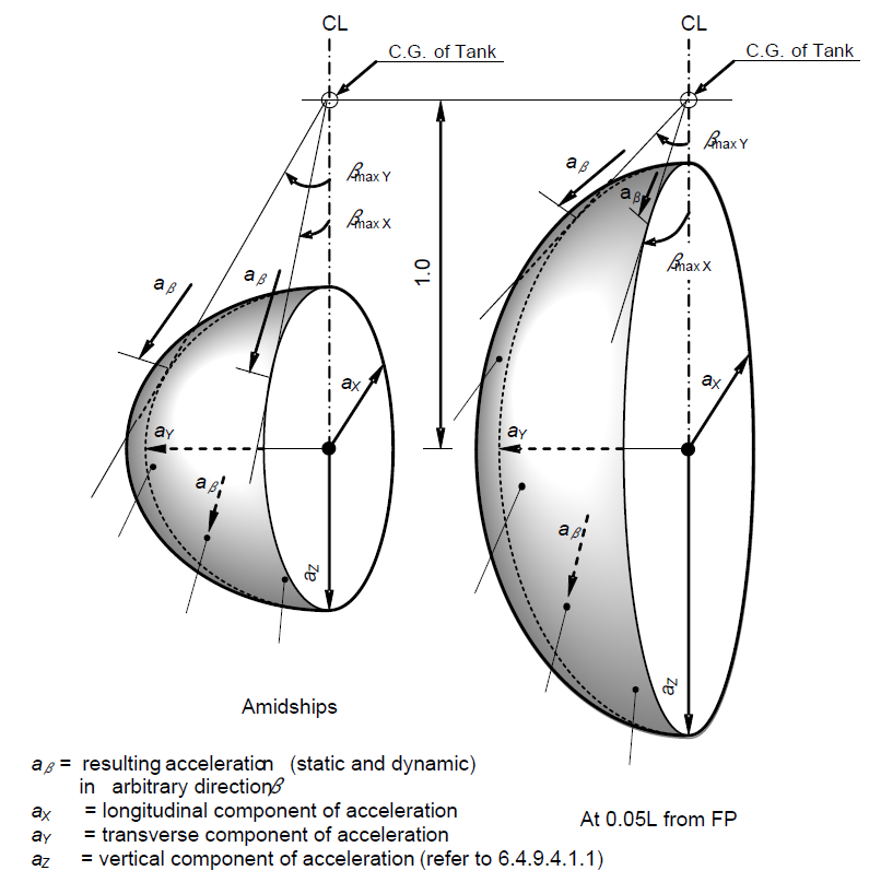
Figure 6.4.1 –
Acceleration ellipsoid
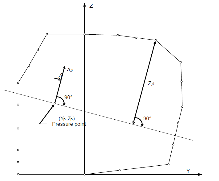
Figure 6.4.2 –
Determination of internal pressure heads
6.4.9.3.3.2 External pressure
External design pressure loads shall be based on the difference between
the minimum internal pressure and the maximum external pressure to which any portion
of the tank may be simultaneously subjected.
6.4.9.3.3.3 Thermally induced loads
6.4.9.3.3.3.1 Transient thermally induced loads during cooling down
periods shall be considered for tanks intended for liquefied gas fuel temperatures
below minus 55°C.
6.4.9.3.3.3.2 Stationary thermally induced loads shall be considered for
liquefied gas fuel containment systems where the design supporting arrangements or
attachments and operating temperature may give rise to significant thermal stresses
(see paragraph 6.9.2).
6.4.9.3.3.4 Vibration
The potentially damaging effects of vibration on the liquefied gas fuel
containment system shall be considered.
6.4.9.3.3.5 Interaction loads
The static component of loads resulting from interaction between
liquefied gas fuel containment system and the hull structure, as well as loads from
associated structure and equipment, shall be considered.
6.4.9.3.3.6 Loads associated with construction and installation
Loads or conditions associated with construction and installation shall
be considered, e.g. lifting.
6.4.9.3.3.7 Test loads
Account shall be taken of the loads corresponding to the testing of the
liquefied gas fuel containment system referred to in 16.5.
6.4.9.3.3.8 Static heel loads
Loads corresponding to the most unfavourable static heel angle within
the range 0° to 30°shall be considered.
6.4.9.3.3.9 Other loads
Any other loads not specifically addressed, which could have an effect
on the liquefied gas fuel containment system, shall be taken into account.
6.4.9.4 Environmental loads
6.4.9.4.1 Environmental loads are defined as those loads on the
liquefied gas fuel containment system that are caused by the surrounding environment
and that are not otherwise classified as a permanent, functional or accidental
load.
6.4.9.4.1.1 Loads due to ship motion
The determination of dynamic loads shall take into account the long-term
distribution of ship motion in irregular seas, which the ship will experience during
its operating life. Account may be taken of the reduction in dynamic loads due to
necessary speed reduction and variation of heading. The ship's motion shall include
surge, sway, heave, roll, pitch and yaw. The accelerations acting on tanks shall be
estimated at their centre of gravity and include the following components:
- .1 vertical acceleration: motion accelerations of heave, pitch and,
possibly roll (normal to the ship base);
- .2 transverse acceleration: motion accelerations of sway, yaw and
roll and gravity component of roll; and
- .3 longitudinal acceleration: motion accelerations of surge and
pitch and gravity component of pitch.
Methods to predict accelerations due to ship motion shall be proposed and
approved by the Administrationfootnote.
Ships for restricted service may be given special consideration.
6.4.9.4.1.2 Dynamic interaction loads
Account shall be taken of the dynamic component of loads resulting from
interaction between liquefied gas fuel containment systems and the hull structure,
including loads from associated structures and equipment.
6.4.9.4.1.3 Sloshing loads
The sloshing loads on a liquefied gas fuel containment system and
internal components shall be evaluated for the full range of intended filling
levels.
6.4.9.4.1.4 Snow and ice loads
Snow and icing shall be considered, if relevant.
6.4.9.4.1.5 Loads due to navigation in ice
Loads due to navigation in ice shall be considered for ships intended for
such service.
6.4.9.4.1.6 Green sea loading
Account shall be taken to loads due to water on deck.
6.4.9.4.1.7 Wind loads
Account shall be taken to wind generated loads as relevant.
6.4.9.5 Accidental loads
Accidental loads are defined as loads that are imposed on a liquefied
gas fuel containment system and it's supporting arrangements under abnormal and
unplanned conditions.
6.4.9.5.1 Collision load
The collision load shall be determined based on the fuel containment
system under fully loaded condition with an inertial force corresponding to "a" in
the table below in forward direction and "a/2" in the aft direction, where "g" is
gravitational acceleration.
| Ship length (L)
|
Design acceleration (a)
|
| L > 100 m
|
0,5 g
|
| 60 < L ≤ 100 m
|

|
| L ≤ 60 m
|
2g
|
Special consideration should be given to ships with Froude number (Fn)
> 0,4.
6.4.9.5.2 Loads due to flooding on ship
For independent tanks, loads caused by the buoyancy of a fully submerged
empty tank shall be considered in the design of anti-flotation chocks and the
supporting structure in both the adjacent hull and tank structure.
6.4.10 Structural integrity
6.4.10.1 General
6.4.10.1.1 The structural design shall ensure that tanks have an
adequate capacity to sustain all relevant loads with an adequate margin of safety.
This shall take into account the possibility of plastic deformation, buckling,
fatigue and loss of liquid and gas tightness.
6.4.10.1.2 The structural integrity of liquefied gas fuel containment
systems can be demonstrated by compliance with 6.4.15, as appropriate for the
liquefied gas fuel containment system type.
6.4.10.1.3 For other liquefied gas fuel containment system types, that
are of novel design or differ significantly from those covered by 6.4.15, the
structural integrity shall be demonstrated by compliance with 6.4.16.
6.4.11 Structural analysis
6.4.11.1 Analysis
6.4.11.1.1 The design analyses shall be based on accepted principles of
statics, dynamics and strength of materials.
6.4.11.1.2 Simplified methods or simplified analyses may be used to
calculate the load effects, provided that they are conservative. Model tests may be
used in combination with, or instead of, theoretical calculations. In cases where
theoretical methods are inadequate, model or full-scale tests may be required.
6.4.11.1.3 When determining responses to dynamic loads, the dynamic
effect shall be taken into account where it may affect structural integrity.
6.4.11.2 Load scenarios
6.4.11.2.1 For each location or part of the liquefied gas fuel
containment system to be considered and for each possible mode of failure to be
analysed, all relevant combinations of loads that may act simultaneously shall be
considered.
6.4.11.2.2 The most unfavourable scenarios for all relevant phases during
construction, handling, testing and in service conditions shall be considered.
6.4.11.2.3 When the static and dynamic stresses are calculated separately
and unless other methods of calculation are justified, the total stresses shall be
calculated according to:
where:
- σx.st, σy.st, σz.st,
τxy.st, τxz.st and τyz.st
are static stresses; and
- σx.dyn, σy.dyn, σz.dyn,
τxy.dyn, τxz.dyn and τyz.dyn
are dynamic stresses,
each shall be determined separately from acceleration components and
hull strain components due to deflection and torsion.
6.4.12 Design conditions
All relevant failure modes shall be considered in the design for all
relevant load scenarios and design conditions. The design conditions are given in
the earlier part of this chapter, and the load scenarios are covered by
6.4.11.2.
6.4.12.1 Ultimate design condition
6.4.12.1.1 Structural capacity may be determined by testing, or by
analysis, taking into account both the elastic and plastic material properties, by
simplified linear elastic analysis or by the provisions of this Code:
-
.2 Analysis shall be based on characteristic load values as follows:
| Permanent
loads
|
Expected
values
|
| Functional
loads
|
Specified
values
|
| Environmental
loads
|
For wave loads:
most probable largest load encountered during
108 wave encounters.
|
-
.3 For the purpose of ultimate strength assessment the following material
parameters apply:
-
.1 Re = specified minimum yield stress at room
temperature (N/mm2). If the stress-strain curve does not
show a defined yield stress, the 0.2% proof stress applies.
-
.2 Rm = specified minimum tensile strength at room
temperature (N/mm2).
- For welded connections where under-matched welds, i.e. where
the weld metal has lower tensile strength than the parent metal,
are unavoidable, such as in some aluminium alloys, the
respective Re and Rm of the
welds, after any applied heat treatment, shall be used. In such
cases the transverse weld tensile strength shall not be less
than the actual yield strength of the parent metal. If this
cannot be achieved, welded structures made from such materials
shall not be incorporated in liquefied gas fuel containment
systems.
-
The above properties shall correspond to the minimum specified
mechanical properties of the material, including the weld metal in
the as fabricated condition. Subject to special consideration by the
Administration, account may be taken of the enhanced yield stress
and tensile strength at low temperature.
-
.4 The equivalent stress σc (von Mises, Huber) shall be
determined by:
-
.5 Allowable stresses for materials other than those covered by 7.4 shall be
subject to approval by the Administration in each case.
6.4.12.2 Fatigue Design Condition
-
.1 The fatigue design condition is the design condition with respect to
accumulated cyclic loading.
-
.2 Where a fatigue analysis is required the cumulative effect of the fatigue
load shall comply with:
-
where:
-
ni = number of stress cycles at each stress level
during the life of the tank;
-
Ni = number of cycles to fracture for the
respective stress level according to the Wohler (S-N)
curve;
-
nLoading = number of loading and unloading cycles
during the life of the tank not to be less than 1000. Loading and
unloading cycles include a complete pressure and thermal cycle;
-
NLoading = number of cycles to fracture for the
fatigue loads due to loading and unloading; and
-
Cw = maximum allowable cumulative fatigue damage
ratio.
-
The fatigue damage shall be based on the design life of the tank but not less
than 108 wave encounters.
-
.3 Where required, the liquefied gas fuel containment system shall be subject
to fatigue analysis, considering all fatigue loads and their appropriate
combinations for the expected life of the liquefied gas fuel containment
system. Consideration shall be given to various filling conditions.
-
.4 Design S-N curves used in the analysis shall be applicable to the
materials and weldments, construction details, fabrication procedures and
applicable state of the stress envisioned.
The S-N curves shall be based on a 97.6% probability of survival
corresponding to the mean-minus-two-standard-deviation curves of relevant
experimental data up to final failure. Use of S-N curves derived in a
different way requires adjustments to the acceptable Cw values specified in
6.4.12.2.7 to 6.4.12.2.9.
-
.5 Analysis shall be based on characteristic load values as follows:
| Permanent loads
|
Expected
values
|
| Functional
loads
|
Specified values or
specified history
|
| Environmental
loads
|
Expected load history,
but not less than 108 cycles
|
If simplified dynamic loading spectra are used for the estimation
of the fatigue life, those shall be specially considered by the
Administration.
-
.6 Where the size of the secondary barrier is reduced, as is provided for in
6.4.2.3, fracture mechanics analyses of fatigue crack growth shall be
carried out to determine:
- .1 crack propagation paths in the structure, where
necessitated by 6.4.12.2.7 to 6.4.12.2.9, as applicable;
- .2 crack growth rate;
- .3 the time required for a crack to propagate to cause a
leakage from the tank;
- .4 the size and shape of through thickness cracks; and
- .5 the time required for detectable cracks to reach a
critical state after penetration through the thickness.
- The fracture mechanics are in general based on crack growth
data taken as a mean value plus two standard deviations of the test
data. Methods for fatigue crack growth analysis and fracture mechanics
shall be based on recognized standards.
- In analysing crack propagation the largest initial crack not
detectable by the inspection method applied shall be assumed, taking
into account the allowable non-destructive testing and visual inspection
criterion as applicable.
- Crack propagation analysis specified in 6.4.12.2.7 the
simplified load distribution and sequence over a period of 15 days may
be used. Such distributions may be obtained as indicated in figure
6.4.3. Load distribution and sequence for longer periods, such as in
6.4.12.2.8 and 6.4.12.2.9 shall be approved by the Administration.
- The arrangements shall comply with 6.4.12.2.7 to 6.4.12.2.9
as applicable.
-
.7 For failures that can be reliably detected by means of leakage
detection:
- Cw shall be less than or equal to
0.5.
- Predicted remaining failure development time, from the point
of detection of leakage till reaching a critical state, shall not be
less than 15 days unless different regulations apply for ships engaged
in particular voyages.
- .
8 For failures that cannot be detected by leakage but that can
be reliably detected at the time of in-service inspections:
- Cw shall be less than or equal to
0.5.
- Predicted remaining failure development time, from the
largest crack not detectable by in-service inspection methods until
reaching a critical state, shall not be less than three (3) times the
inspection interval.
-
.9 In particular locations of the tank where effective defect or crack
development detection cannot be assured, the following, more stringent,
fatigue acceptance criteria shall be applied as a minimum:
- Cw shall be less than or equal to
0.1.
- Predicted failure development time, from the assumed
initial defect until reaching a critical state, shall not be less than
three (3) times the lifetime of the tank.
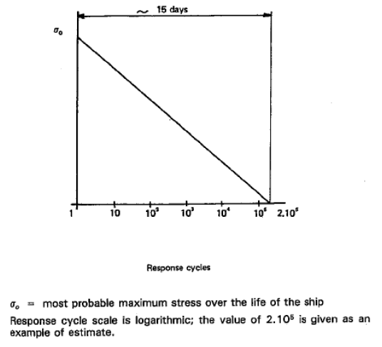
Figure 6.4.3 – Simplified load
distribution
6.4.12.3 Accidental design condition
6.4.12.3.1 The accidental design condition is a design condition for
accidental loads with extremely low probability of occurrence.
6.4.12.3.2 Analysis shall be based on the characteristic values as
follows:
| Permanent loads
|
Expected values
|
| Functional loads
|
Specified values
|
| Environmental loads
|
Specified values
|
| Accidental loads
|
Specified values or expected
values
|
Loads mentioned in 6.4.9.3.3.8 and 6.4.9.5 need not be combined with
each other or with wave-induced loads.
6.4.13 Materials and construction
6.4.13.1 Materials
6.4.13.1.1 Materials forming ship structure
6.4.13.1.1.1 To determine the grade of plate and sections used in the
hull structure, a temperature calculation shall be performed for all tank types. The
following assumptions shall be made in this calculation:
- .1 The primary barrier of all tanks shall be assumed to be at the
liquefied gas fuel temperature.
- .2 In addition to .1 above, where a complete or partial secondary
barrier is required it shall be assumed to be at the liquefied gas fuel
temperature at atmospheric pressure for any one tank only.
- .3 For worldwide service, ambient temperatures shall be taken as
5°C for air and 0°C for seawater. Higher values may be accepted for ships
operating in restricted areas and conversely, lower values may be imposed by the
Administration for ships trading to areas where lower temperatures are expected
during the winter months.
- .4 Still air and sea water conditions shall be assumed, i.e. no
adjustment for forced convection.
- .5 Degradation of the thermal insulation properties over the life
of the ship due to factors such as thermal and mechanical ageing, compaction,
ship motions and tank vibrations as defined in 6.4.13.3.6 and 6.4.13.3.7 shall
be assumed.
- .6 The cooling effect of the rising boil-off vapour from the
leaked liquefied gas fuel shall be taken into account where applicable.
- .7 Credit for hull heating may be taken in accordance with
6.4.13.1.1.3, provided the heating arrangements are in compliance with
6.4.13.1.1.4.
- .8 No credit shall be given for any means of heating, except as
described in 6.4.13.1.1.3.
- .9 For members connecting inner and outer hulls, the mean
temperature may be taken for determining the steel grade.
6.4.13.1.1.2 The materials of all hull structures for which the
calculated temperature in the design condition is below 0°C, due to the influence of
liquefied gas fuel temperature, shall be in accordance with table 7.5. This includes
hull structure supporting the liquefied gas fuel tanks, inner bottom plating,
longitudinal bulkhead plating, transverse bulkhead plating, floors, webs, stringers
and all attached stiffening members.
6.4.13.1.1.3 Means of heating structural materials may be used to ensure
that the material temperature does not fall below the minimum allowed for the grade
of material specified in table 7.5. In the calculations required in 6.4.13.1.1.1,
credit for such heating may be taken in accordance with the following
principles:
- .1 for any transverse hull structure;
- .2 for longitudinal hull structure referred to in 6.4.13.1.1.2
where colder ambient temperatures are specified, provided the material remains
suitable for the ambient temperature conditions of plus 5°C for air and 0°C for
seawater with no credit taken in the calculations for heating; and
- .3 as an alternative to 6.4.13.1.1.3.2, for longitudinal bulkhead
between liquefied gas fuel tanks, credit may be taken for heating provided the
material remain suitable for a minimum design temperature of minus 30°C, or a
temperature 30°C lower than that determined by 6.4.13.1.1.1 with the heating
considered, whichever is less. In this case, the ship's longitudinal strength
shall comply with SOLAS regulation II-1/3-1 for both when
those bulkhead(s) are considered effective and not.
6.4.13.1.1.4 The means of heating referred to in 6.4.13.1.1.3 shall
comply with the following:
- .1 the heating system shall be arranged so that, in the event of
failure in any part of the system, standby heating can be maintained equal to no
less than 100% of the theoretical heat requirement;
- .2 the heating system shall be considered as an essential
auxiliary. All electrical components of at least one of the systems provided in
accordance with 6.4.13.1.1.3.1 shall be supplied from the emergency source of
electrical power; and
- .3 the design and construction of the heating system shall be
included in the approval of the containment system by the Administration.
6.4.13.2 Materials of primary and secondary barriers
6.4.13.2.1 Metallic materials used in the construction of primary and
secondary barriers not forming the hull, shall be suitable for the design loads that
they may be subjected to, and be in accordance with table 7.1, 7.2 or 7.3.
6.4.13.2.2 Materials, either non-metallic or metallic but not covered by
tables 7.1, 7.2 and 7.3, used in the primary and secondary barriers may be approved
by the Administration considering the design loads that they may be subjected to,
their properties and their intended use.
6.4.13.2.3 Where non-metallic materials,footnote including composites, are used for or
incorporated in the primary or secondary barriers, they shall be tested for the
following properties, as applicable, to ensure that they are adequate for the
intended service:
- .1 compatibility with the liquefied gas fuels;
- .2 ageing;
- .3 mechanical properties;
- .4 thermal expansion and contraction;
- .5 abrasion;
- .6 cohesion;
- .7 resistance to vibrations;
- .8 resistance to fire and flame spread; and
- .9 resistance to fatigue failure and crack propagation.
6.4.13.2.4 The above properties, where applicable, shall be tested for
the range between the expected maximum temperature in service and 5°C below the
minimum design temperature, but not lower than minus196°C.
6.4.13.2.5 Where non-metallic materials, including composites, are used
for the primary and secondary barriers, the joining processes shall also be tested
as described above.
6.4.13.2.6 Consideration may be given to the use of materials in the
primary and secondary barrier, which are not resistant to fire and flame spread,
provided they are protected by a suitable system such as a permanent inert gas
environment, or are provided with a fire retardant barrier.
6.4.13.3 Thermal insulation and other materials used in liquefied gas
fuel containment systems
6.4.13.3.1 Load-bearing thermal insulation and other materials used in
liquefied gas fuel containment systems shall be suitable for the design loads.
6.4.13.3.2 Thermal insulation and other materials used in liquefied gas
fuel containment systems shall have the following properties, as applicable, to
ensure that they are adequate for the intended service:
- .1 compatibility with the liquefied gas fuels;
- .2 solubility in the liquefied gas fuel;
- .3 absorption of the liquefied gas fuel;
- .4 shrinkage;
- .5 ageing;
- .6 closed cell content;
- .7 density;
- .8 mechanical properties, to the extent that they are subjected to
liquefied gas fuel and other loading effects, thermal expansion and contraction;
- .9 abrasion;
- .10 cohesion;
- .11 thermal conductivity;
- .12 resistance to vibrations;
- .13 resistance to fire and flame spread; and
- .14 resistance to fatigue failure and crack propagation.
6.4.13.3.3 The above properties, where applicable, shall be tested for
the range between the expected maximum temperature in service and 5°C below the
minimum design temperature, but not lower than minus 196°C.
6.4.13.3.4 Due to location or environmental conditions, thermal
insulation materials shall have suitable properties of resistance to fire and flame
spread and shall be adequately protected against penetration of water vapour and
mechanical damage. Where the thermal insulation is located on or above the exposed
deck, and in way of tank cover penetrations, it shall have suitable fire resistance
properties in accordance with a recognized standard or be covered with a material
having low flame spread characteristics and forming an efficient approved vapour
seal.
6.4.13.3.5 Thermal insulation that does not meet recognized standards
for fire resistance may be used in fuel storage hold spaces that are not kept
permanently inerted, provided its surfaces are covered with material with low flame
spread characteristics and that forms an efficient approved vapour seal.
6.4.13.3.6 Testing for thermal conductivity of thermal insulation shall
be carried out on suitably aged samples.
6.4.13.3.7 Where powder or granulated thermal insulation is used,
measures shall be taken to reduce compaction in service and to maintain the required
thermal conductivity and also prevent any undue increase of pressure on the
liquefied gas fuel containment system.
6.4.14 Construction processes
6.4.14.1 Weld joint design
6.4.14.1.1 All welded joints of the shells of independent tanks shall be
of the in-plane butt weld full penetration type. For dome-to-shell connections only,
tee welds of the full penetration type may be used depending on the results of the
tests carried out at the approval of the welding procedure. Except for small
penetrations on domes, nozzle welds are also to be designed with full
penetration.
6.4.14.1.2 Welding joint details for type C independent tanks, and for
the liquid-tight primary barriers of type B independent tanks primarily constructed
of curved surfaces, shall be as follows:
- .1 All longitudinal and circumferential joints shall be of butt
welded, full penetration, double vee or single vee type. Full penetration butt
welds shall be obtained by double welding or by the use of backing rings. If
used, backing rings shall be removed except from very small process pressure
vessels.footnote Other edge preparations may be
permitted, depending on the results of the tests carried out at the approval of
the welding procedure. For connections of tank shell to a longitudinal bulkhead
of type C bilobe tanks, tee welds of the full penetration type may be accepted.
- .2 The bevel preparation of the joints between the tank body and
domes and between domes and relevant fittings shall be designed according to a
standard acceptable to the Administration. All welds connecting nozzles, domes
or other penetrations of the vessel and all welds connecting flanges to the
vessel or nozzles shall be full penetration welds.
6.4.14.2 Design for gluing and other joining processes
6.4.14.2.1 The design of the joint to be glued (or joined by some other
process except welding) shall take account of the strength characteristics of the
joining process.
6.4.15 Tank types
6.4.15.1 Type A independent tanks
6.4.15.1.1 Design basis
6.4.15.1.1.1 Type A independent tanks are tanks primarily designed using
classical ship-structural analysis procedures in accordance with the requirements of
the Administration. Where such tanks are primarily constructed of plane surfaces,
the design vapour pressure P0 shall be less than 0.07 MPa.
6.4.15.1.1.2 A complete secondary barrier is required as defined in
6.4.3. The secondary barrier shall be designed in accordance with 6.4.4.
6.4.15.1.2 Structural analysis
6.4.15.1.2.1 A structural analysis shall be performed taking into
account the internal pressure as indicated in 6.4.9.3.3.1, and the interaction loads
with the supporting and keying system as well as a reasonable part of the ship's
hull.
6.4.15.1.2.2 For parts, such as structure in way of supports, not
otherwise covered by the regulations in this Code, stresses shall be determined by
direct calculations, taking into account the loads referred to in 6.4.9.2 to 6.4.9.5
as far as applicable, and the ship deflection in way of supports.
6.4.15.1.2.3 The tanks with supports shall be designed for the
accidental loads specified in 6.4.9.5. These loads need not be combined with each
other or with environmental loads.
6.4.15.1.3 Ultimate design condition
6.4.15.1.3.1 For tanks primarily constructed of plane surfaces, the
nominal membrane stresses for primary and secondary members (stiffeners, web frames,
stringers, girders), when calculated by classical analysis procedures, shall not
exceed the lower of Rm/2.66 or Re/1.33 for nickel steels,
carbon-manganese steels, austenitic steels and aluminium alloys, where Rm
and Re are defined in 6.4.12.1.1.3. However, if detailed calculations are
carried out for the primary members, the equivalent stress σc, as defined in
6.4.12.1.1.4, may be increased over that indicated above to a stress acceptable to
the Administration. Calculations shall take into account the effects of bending,
shear, axial and torsional deformation as well as the hull/liquefied gas fuel tank
interaction forces due to the deflection of the hull structure and liquefied gas
fuel tank bottoms.
6.4.15.1.3.2 Tank boundary scantlings shall meet at least the
requirements of the Administration for deep tanks taking into account the internal
pressure as indicated in 6.4.9.3.3.1 and any corrosion allowance required by
6.4.1.7.
6.4.15.1.3.3 The liquefied gas fuel tank structure shall be reviewed
against potential buckling.
6.4.15.1.4 Accidental design condition
6.4.15.1.4.1 The tanks and the tank supports shall be designed for the
accidental loads and design conditions specified in 6.4.9.5 and 6.4.1.6.3 as
relevant.
6.4.15.1.4.2 When subjected to the accidental loads specified in
6.4.9.5, the stress shall comply with the acceptance criteria specified in
6.4.15.1.3, modified as appropriate taking into account their lower probability of
occurrence.
6.4.15.2 Type B independent tanks
6.4.15.2.1 Design basis
6.4.15.2.1.1 Type B independent tanks are tanks designed using model
tests, refined analytical tools and analysis methods to determine stress levels,
fatigue life and crack propagation characteristics. Where such tanks are primarily
constructed of plane surfaces (prismatic tanks) the design vapour pressure
P0 shall be less than 0.07 MPa.
6.4.15.2.1.2 A partial secondary barrier with a protection system is
required as defined in 6.4.3. The small leak protection system shall be designed
according to 6.4.5.
6.4.15.2.2 Structural analysis
6.4.15.2.2.1 The effects of all dynamic and static loads shall be used
to determine the suitability of the structure with respect to:
- .1 plastic deformation;
- .2 buckling;
- .3 fatigue failure; and
- .4 crack propagation.
Finite element analysis or similar methods and fracture mechanics
analysis or an equivalent approach, shall be carried out.
6.4.15.2.2.2 A three-dimensional analysis shall be carried out to
evaluate the stress levels, including interaction with the ship's hull. The model
for this analysis shall include the liquefied gas fuel tank with its supporting and
keying system, as well as a reasonable part of the hull.
6.4.15.2.2.3 A complete analysis of the particular ship accelerations
and motions in irregular waves, and of the response of the ship and its liquefied
gas fuel tanks to these forces and motions, shall be performed unless the data is
available from similar ships.
6.4.15.2.3 Ultimate design condition
6.4.15.2.3.1 Plastic deformation
For type B independent tanks, primarily constructed of bodies of
revolution, the allowable stresses shall not exceed:
- σm ≤ f
- σL ≤ 1.5f
- σb ≤ 1.5F
- σL + σb ≤ 1.5F
- σm + σb ≤ 1.5F
- σm + σb + σg
≤ 3.0F
- σL + σb + σg
≤ 3.0F
where:
- σm = equivalent primary general membrane
stress;
- σL = equivalent primary local membrane stress;
- σb = equivalent primary bending stress;
- σg = equivalent secondary stress;
- f = the lesser of (Rm / A) or (Re
/ B); and
- F = the lesser of (Rm / C) or (Re
/ D),
with Rmand Re
as defined in 6.4.12.1.1.3. With regard to the stresses σm,
σL ,
σg and σb see also the definition of stress
categories in 6.4.15.2.3.6.
The values A and B shall have at least the following minimum values:
|
|
Nickel steels and carbon manganese
steels
|
Austenitic steel
|
Aluminium alloys
|
| A
|
3
|
3.5
|
4
|
| B
|
2
|
1.6
|
1.5
|
| C
|
3
|
3
|
3
|
| D
|
1.5
|
1.5
|
1.5
|
The above figures may be altered considering the design condition
considered in acceptance with the Administration. For type B independent tanks,
primarily constructed of plane surfaces, the allowable membrane equivalent stresses
applied for finite element analysis shall not exceed:
- .1 for nickel steels and carbon-manganese steels, the lesser of
Rm /2 or Re /1.2;
- .2 for austenitic steels, the lesser of Rm /2.5
or Re /1.2; and
- .3 for aluminium alloys, the lesser of Rm /2.5
or Re /1.2.
The above figures may be amended considering the locality of the stress,
stress analysis methods and design condition considered in acceptance with the
Administration.
The thickness of the skin plate and the size of the stiffener shall not
be less than those required for type A independent tanks.
6.4.15.2.3.2 Buckling
Buckling strength analyses of liquefied gas fuel tanks subject to
external pressure and other loads causing compressive stresses shall be carried out
in accordance with recognized standards. The method shall adequately account for the
difference in theoretical and actual buckling stress as a result of plate edge
misalignment, lack of straightness or flatness, ovality and deviation from true
circular form over a specified arc or chord length, as applicable.
6.4.15.2.3.3 Fatigue design condition
6.4.15.2.3.3.1 Fatigue and crack propagation assessment shall be
performed in accordance with the provisions of 6.4.12.2. The acceptance criteria
shall comply with 6.4.12.2.7, 6.4.12.2.8 or 6.4.12.2.9, depending on the
detectability of the defect.
6.4.15.2.3.3.2 Fatigue analysis shall consider construction tolerances.
6.4.15.2.3.3.3 Where deemed necessary by the Administration, model tests
may be required to determine stress concentration factors and fatigue life of
structural elements.
6.4.15.2.3.4 Accidental design condition
6.4.15.2.3.4.1 The tanks and the tank supports shall be designed for the
accidental loads and design conditions specified in 6.4.9.5 and 6.4.1.6.3, as
relevant.
6.4.15.2.3.4.2 When subjected to the accidental loads specified in
6.4.9.5, the stress shall comply with the acceptance criteria specified in
6.4.15.2.3, modified as appropriate, taking into account their lower probability of
occurrence.
6.4.15.2.3.5 Marking
Any marking of the pressure vessel shall be achieved by a method that
does not cause unacceptable local stress raisers.
6.4.15.2.3.6 Stress categories
For the purpose of stress evaluation, stress categories are defined in
this section as follows:
-
.1 Normal stress is the component of stress normal to the plane of
reference.
-
.2 Membrane stress is the component of normal stress that is uniformly
distributed and equal to the average value of the stress across the
thickness of the section under consideration.
-
.3 Bending stress is the variable stress across the thickness of the
section under consideration, after the subtraction of the membrane stress.
-
.4 Shear stress is the component of the stress acting in the plane of
reference.
-
.5 Primary stress is a stress produced by the imposed loading, which
is necessary to balance the external forces and moments. The basic
characteristic of a primary stress is that it is not self-limiting. Primary
stresses that considerably exceed the yield strength will result in failure
or at least in gross deformations.
-
.6 Primary general membrane stress is a primary membrane stress that
is so distributed in the structure that no redistribution of load occurs as
a result of yielding.
-
.7 Primary local membrane stress arises where a membrane stress
produced by pressure or other mechanical loading and associated with a
primary or a discontinuity effect produces excessive distortion in the
transfer of loads for other portions of the structure. Such a stress is
classified as a primary local membrane stress, although it has some
characteristics of a secondary stress. A stress region may be considered as
local, if:
- where:
-
S1 = distance in the meridional direction over
which the equivalent stress exceeds 1.1f;
-
S2 = distance in the meridional direction to
another region where the limits for primary general membrane stress
are exceeded;
-
R = mean radius of the vessel;
-
t = wall thickness of the vessel at the location where the
primary general membrane stress limit is exceeded; and
-
f = allowable primary general membrane stress.
-
.8 Secondary stress is a normal stress or shear stress developed by
constraints of adjacent parts or by self-constraint of a structure. The
basic characteristic of a secondary stress is that it is self-limiting.
Local yielding and minor distortions can satisfy the conditions that cause
the stress to occur.
6.4.15.3 Type C independent tanks
6.4.15.3.1 Design basis
6.4.15.3.1.1 The design basis for type C independent tanks is based on
pressure vessel criteria modified to include fracture mechanics and crack
propagation criteria. The minimum design pressure defined in 6.4.15.3.1.2 is
intended to ensure that the dynamic stress is sufficiently low so that an initial
surface flaw will not propagate more than half the thickness of the shell during the
lifetime of the tank.
6.4.15.3.1.2 The design vapour pressure shall not be less than:
- P0 = 0.2 +
AC(ρr)1.5 (MPa)
where:
6.4.15.3.2 Shell thickness
6.4.15.3.2.1 In considering the shell thickness the following apply:
- .1 for pressure vessels, the thickness calculated according to
6.4.15.3.2.4 shall be considered as a minimum thickness after forming, without
any negative tolerance;
- .2 for pressure vessels, the minimum thickness of shell and heads
including corrosion allowance, after forming, shall not be less than 5 mm for
carbon manganese steels and nickel steels, 3 mm for austenitic steels or 7 mm
for aluminium alloys; and
- .3 the welded joint efficiency factor to be used in the calculation
according to 6.4.15.3.2.4 shall be 0.95 when the inspection and the
non-destructive testing referred to in 16.3.6.4 are carried out. This figure may
be increased up to 1.0 when account is taken of other considerations, such as
the material used, type of joints, welding procedure and type of loading. For
process pressure vessels the Administration may accept partial non-destructive
examinations, but not less than those of 16.3.6.4, depending on such factors as
the material used, the design temperature, the nil ductility transition
temperature of the material as fabricated and the type of joint and welding
procedure, but in this case an efficiency factor of not more than 0.85 shall be
adopted. For special materials the above-mentioned factors shall be reduced,
depending on the specified mechanical properties of the welded joint.
6.4.15.3.2.2 The design liquid pressure defined in 6.4.9.3.3.1 shall be
taken into account in the internal pressure calculations.
6.4.15.3.2.3 The design external pressure Pe, used for
verifying the buckling of the pressure vessels, shall not be less than that given
by:
Pe = P1 + P2 +
P3 + P4 (MPa)
where:
- P1 = setting value of vacuum relief valves. For
vessels not fitted with vacuum relief valves P1shall be
specially considered, but shall not in general be taken as less than 0.025 MPa.
- P2 = the set pressure of the pressure relief
valves (PRVs) for completely closed spaces containing pressure vessels or parts
of pressure vessels; elsewhere P2= 0.
- P3 = compressive actions in or on the shell due
to the weight and contraction of thermal insulation, weight of shell including
corrosion allowance and other miscellaneous external pressure loads to which the
pressure vessel may be subjected. These include, but are not limited to, weight
of domes, weight of towers and piping, effect of product in the partially filled
condition, accelerations and hull deflection. In addition, the local effect of
external or internal pressures or both shall be taken into account.
- P4 = external pressure due to head of water for
pressure vessels or part of pressure vessels on exposed decks; elsewhere
P4= 0.
6.4.15.3.2.4 Scantlings based on internal pressure shall be calculated
as follows:
The thickness and form of pressure-containing parts of pressure vessels,
under internal pressure, as defined in 6.4.9.3.3.1, including flanges, shall be
determined. These calculations shall in all cases be based on accepted pressure
vessel design theory. Openings in pressure-containing parts of pressure vessels
shall be reinforced in accordance with a recognized standard acceptable to the
Administration.
6.4.15.3.2.5 Stress analysis in respect of static and dynamic loads
shall be performed as follows:
- .1 pressure vessel scantlings shall be determined in accordance
with 6.4.15.3.2.1 to 6.4.15.3.2.4 and 6.4.15.3.3;
- .2 calculations of the loads and stresses in way of the supports
and the shell attachment of the support shall be made. Loads referred to in
6.4.9.2 to 6.4.9.5 shall be used, as applicable. Stresses in way of the supports
shall be to a recognized standard acceptable to the Administration. In special
cases a fatigue analysis may be required by the Administration; and
- .3 if required by the Administration, secondary stresses and
thermal stresses shall be specially considered.
6.4.15.3.3 Ultimate design condition
6.4.15.3.3.1 Plastic deformation
For type C independent tanks, the allowable stresses shall not exceed:
- σm ≤ f
- σL ≤ 1.5f
- σb ≤ 1.5f
- σL + σb ≤ 1.5f
- σm + σb ≤ 1.5f
- σm + σb + σg
≤ 3.0f
- σL + σb + σg
≤ 3.0f
where:
- σm = equivalent primary general membrane stress;
- σL = equivalent primary local membrane stress;
- σb = equivalent primary bending stress;
- σg = equivalent secondary stress; and
- f = the lesser of Rm/A or
Re/B,
- with Rm and Reas defined in
6.4.12.1.1.3. With regard to the stresses σm , σL,
σg and σb see also the
definition of stress categories in 6.4.15.2.3.6. The values A and B shall have
at least the following minimum values:
|
|
Nickel steels and carbon-manganese
steels
|
Austenitic steels
|
Aluminium alloys
|
| A
|
3
|
3.5
|
4
|
| B
|
1.5
|
1.5
|
1.5
|
6.4.15.3.3.2 Buckling criteria shall be as follows:
The thickness and form of pressure vessels subject to external pressure
and other loads causing compressive stresses shall be based on calculations using
accepted pressure vessel buckling theory and shall adequately account for the
difference in theoretical and actual buckling stress as a result of plate edge
misalignment, ovality and deviation from true circular form over a specified arc or
chord length.
6.4.15.3.4 Fatigue design condition
6.4.15.3.4.1 For type C independent tanks where the liquefied gas fuel
at atmospheric pressure is below minus 55°C, the Administration may require
additional verification to check their compliance with 6.4.15.3.1.1, regarding
static and dynamic stress depending on the tank size, the configuration of the tank
and arrangement of its supports and attachments.
6.4.15.3.4.2 For vacuum insulated tanks, special attention shall be made
to the fatigue strength of the support design and special considerations shall also
be made to the limited inspection possibilities between the inside and outer shell.
6.4.15.3.5 Accidental design condition
6.4.15.3.5.1 The tanks and the tank supports shall be designed for the
accidental loads and design conditions specified in 6.4.9.5 and 6.4.1.6.3, as
relevant.
6.4.15.3.5.2 When subjected to the accidental loads specified in 6.4.9.5,
the stress shall comply with the acceptance criteria specified in 6.4.15.3.3.1,
modified as appropriate taking into account their lower probability of occurrence.
6.4.15.3.6 Marking
The required marking of the pressure vessel shall be achieved by a
method that does not cause unacceptable local stress raisers.
6.4.15.4 Membrane tanks
6.4.15.4.1 Design basis
6.4.15.4.1.1 The design basis for membrane containment systems is that
thermal and other expansion or contraction is compensated for without undue risk of
losing the tightness of the membrane.
6.4.15.4.1.2 A systematic approach, based on analysis and testing, shall
be used to demonstrate that the system will provide its intended function in
consideration of the identified in service events as specified in 6.4.15.4.2.1.
6.4.15.4.1.3 A complete secondary barrier is required as defined in
6.4.3. The secondary barrier shall be designed according to 6.4.4.
6.4.15.4.1.4 The design vapour pressure P0 shall not normally
exceed 0.025 MPa. If the hull scantlings are increased accordingly and consideration
is given, where appropriate, to the strength of the supporting thermal insulation,
P0 may be increased to a higher value but less than 0.070 MPa.
6.4.15.4.1.5 The definition of membrane tanks does not exclude designs
such as those in which non-metallic membranes are used or where membranes are
included or incorporated into the thermal insulation.
6.4.15.4.1.6 The thickness of the membranes shall normally not exceed 10
mm.
6.4.15.4.1.7 The circulation of inert gas throughout the primary and the
secondary insulation spaces, in accordance with 6.11.1 shall be sufficient to allow
for effective means of gas detection.
6.4.15.4.2 Design considerations
6.4.15.4.2.1 Potential incidents that could lead to loss of fluid
tightness over the life of the membranes shall be evaluated. These include, but are
not limited to:
- .1 Ultimate design events:
- .1 tensile failure of membranes;
- .2 compressive collapse of thermal insulation;
- .3 thermal ageing;
- .4 loss of attachment between thermal insulation and hull
structure;
- .5 loss of attachment of membranes to thermal insulation
system;
- .6 structural integrity of internal structures and their
associated supporting structures; and
- .7 failure of the supporting hull structure.
- .2 Fatigue design events:
- .1 fatigue of membranes including joints and attachments to
hull structure;
- .2 fatigue cracking of thermal insulation;
- .3 fatigue of internal structures and their associated
supporting structures; and
- .4 fatigue cracking of inner hull leading to ballast water
ingress.
- .3 Accident design events:
- .1 accidental mechanical damage (such as dropped objects
inside the tank while in service);
- .2 accidental over pressurization of thermal insulation
spaces;
- .3 accidental vacuum in the tank; and
- .4 water ingress through the inner hull structure.
Designs where a single internal event could cause simultaneous or
cascading failure of both membranes are unacceptable.
6.4.15.4.2.2 The necessary physical properties (mechanical, thermal,
chemical, etc.) of the materials used in the construction of the liquefied gas fuel
containment system shall be established during the design development in accordance
with 6.4.15.4.1.2.
6.4.15.4.3 Loads, load combinations
Particular consideration shall be paid to the possible loss of tank
integrity due to either an overpressure in the interbarrier space, a possible vacuum
in the liquefied gas fuel tank, the sloshing effects, to hull vibration effects, or
any combination of these events.
6.4.15.4.4 Structural analyses
6.4.15.4.4.1 Structural analyses and/or testing for the purpose of
determining the ultimate strength and fatigue assessments of the liquefied gas fuel
containment and associated structures and equipment noted in 6.4.7 shall be
performed. The structural analysis shall provide the data required to assess each
failure mode that has been identified as critical for the liquefied gas fuel
containment system.
6.4.15.4.4.2 Structural analyses of the hull shall take into account the
internal pressure as indicated in 6.4.9.3.3.1. Special attention shall be paid to
deflections of the hull and their compatibility with the membrane and associated
thermal insulation.
6.4.15.4.4.3 The analyses referred to in 6.4.15.4.4.1 and 6.4.15.4.4.2
shall be based on the particular motions, accelerations and response of ships and
liquefied gas fuel containment systems.
6.4.15.4.5 Ultimate design condition
6.4.15.4.5.1 The structural resistance of every critical component,
sub-system, or assembly, shall be established, in accordance with 6.4.15.4.1.2, for
in-service conditions.
6.4.15.4.5.2 The choice of strength acceptance criteria for the failure
modes of the liquefied gas fuel containment system, its attachments to the hull
structure and internal tank structures, shall reflect the consequences associated
with the considered mode of failure.
6.4.15.4.5.3 The inner hull scantlings shall meet the regulations for
deep tanks, taking into account the internal pressure as indicated in 6.4.9.3.3.1
and the specified appropriate regulations for sloshing load as defined in
6.4.9.4.1.3.
6.4.15.4.6 Fatigue design condition
6.4.15.4.6.1 Fatigue analysis shall be carried out for structures inside
the tank, i.e. pump towers, and for parts of membrane and pump tower attachments,
where failure development cannot be reliably detected by continuous monitoring.
6.4.15.4.6.2 The fatigue calculations shall be carried out in accordance
with 6.4.12.2, with relevant regulations depending on:
- .1 the significance of the structural components with respect
to structural integrity; and
- .2 availability for inspection.
6.4.15.4.6.3 For structural elements for which it can be demonstrated by
tests and/or analyses that a crack will not develop to cause simultaneous or
cascading failure of both membranes, Cw shall be less than or
equal to 0.5.
6.4.15.4.6.4 Structural elements subject to periodic inspection, and
where an unattended fatigue crack can develop to cause simultaneous or cascading
failure of both membranes, shall satisfy the fatigue and fracture mechanics
regulations stated in 6.4.12.2.8.
6.4.15.4.6.5 Structural element not accessible for in-service
inspection, and where a fatigue crack can develop without warning to cause
simultaneous or cascading failure of both membranes, shall satisfy the fatigue and
fracture mechanics regulations stated in 6.4.12.2.9.
6.4.15.4.7 Accidental design condition
6.4.15.4.7.1 The containment system and the supporting hull structure shall be
designed for the accidental loads specified in 6.4.9.5. These loads need not be
combined with each other or with environmental loads.
6.4.15.4.7.2 Additional relevant accidental scenarios shall be determined based on a
risk analysis. Particular attention shall be paid to securing devices inside of
tanks.
6.4.16 Limit state design for novel concepts
6.4.16.1 Fuel containment systems that are of a novel configuration that cannot be
designed using section 6.4.15 shall be designed using this section and 6.4.1 to
6.4.14, as applicable. Fuel containment system design according to this section
shall be based on the principles of limit state design which is an approach to
structural design that can be applied to established design solutions as well as
novel designs. This more generic approach maintains a level of safety similar to
that achieved for known containment systems as designed using 6.4.15.
6.4.16.2 The limit state design is a systematic approach where each
structural element is evaluated with respect to possible failure modes related to
the design conditions identified in 6.4.1.6. A limit state can be defined as a
condition beyond which the structure, or part of a structure, no longer satisfies
the regulations.
6.4.16.3 For each failure mode, one or more limit states may be
relevant. By consideration of all relevant limit states, the limit load for the
structural element is found as the minimum limit load resulting from all the
relevant limit states. The limit states are divided into the three following
categories:
-
.1 Ultimate limit states (ULS), which correspond to the maximum
load-carrying capacity or, in some cases, to the maximum applicable strain
or deformation; under intact (undamaged) conditions.
-
.2 Fatigue limit states (FLS), which correspond to degradation
due to the effect of time varying (cyclic) loading.
-
.3 Accident limit states (ALS), which concern the ability of the
structure to resist accidental situations.
6.4.16.4 The procedure and relevant design parameters of the limit state
design shall comply with the Standards for the Use of limit state methodologies in
the design of fuel containment systems of novel configuration (LSD Standard), as set
out in the annex to part A-1.
6.5 Regulations for portable liquefied gas fuel tanks
6.5.1 The design of the tank shall comply with 6.4.15.3. The tank support (container
frame or truck chassis) shall be designed for the intended purpose.
6.5.2 Portable fuel tanks shall be located in dedicated areas fitted with:
- .1 mechanical protection of the tanks depending on location and cargo
operations;
- .2 if located on open deck: spill protection and water spray systems for
cooling; and
- .3 if located in an enclosed space: the space is to be considered as a tank
connection space.
6.5.3 Portable fuel tanks shall be secured to the deck while connected to the ship
systems. The arrangement for supporting and fixing the tanks shall be designed for
the maximum expected static and dynamic inclinations, as well as the maximum
expected values of acceleration, taking into account the ship characteristics and
the position of the tanks.
6.5.4 Consideration shall be given to the strength and the effect of the portable
fuel tanks on the ship's stability.
6.5.5 Connections to the ship's fuel piping systems shall be made by means of
approved flexible hoses or other suitable means designed to provide sufficient
flexibility.
6.5.6 Arrangements shall be provided to limit the quantity of fuel spilled in case of
inadvertent disconnection or rupture of the non-permanent connections.
6.5.7 The pressure relief system of portable tanks shall be connected to a fixed
venting system.
6.5.8 Control and monitoring systems for portable fuel tanks shall be integrated in
the ship's control and monitoring system. Safety system for portable fuel tanks
shall be integrated in the ship's safety system (e.g. shutdown systems for tank
valves, leak/gas detection systems).
6.5.9 Safe access to tank connections for the purpose of inspection and maintenance
shall be ensured.
6.5.10 After connection to the ship's fuel piping system,
- .1 with the exception of the pressure relief system in 6.5.6 each portable tank
shall be capable of being isolated at any time;
- .2 isolation of one tank shall not impair the availability of the remaining
portable tanks; and
- .3 the tank shall not exceed its filling limits as given in 6.8.
6.6 Regulations for CNG fuel containment
6.6.1 The storage tanks to be used for CNG shall be certified and approved by the
Administration.
6.6.2 Tanks for CNG shall be fitted with pressure relief valves with a set point
below the design pressure of the tank and with outlet located as required in 6.7.2.7
and 6.7.2.8.
6.6.3 Adequate means shall be provided to depressurize the tank in case of a fire
which can affect the tank.
6.6.4 Storage of CNG in enclosed spaces is normally not acceptable, but may be
permitted after special consideration and approval by the Administration provided
the following is fulfilled in addition to 6.3.4 to 6.3.6:
- .1 adequate means are provided to depressurize and inert the tank in case of a
fire which can affect the tank;
- .2 all surfaces within such enclosed spaces containing the CNG storage are
provided with suitable thermal protection against any lost high-pressure gas and
resulting condensation unless the bulkheads are designed for the lowest
temperature that can arise from gas expansion leakage; and
- .3 a fixed fire-extinguishing system is installed in the enclosed spaces
containing the CNG storage. Special consideration should be given to the
extinguishing of jet-fires.
6.7 Regulations for pressure
relief system
6.7.1 General
6.7.1.1 All fuel storage tanks shall be provided with a pressure relief
system appropriate to the design of the fuel containment system and the fuel being
carried. Fuel storage hold spaces, interbarrier spaces, tank connection spaces and
tank cofferdams, which may be subject to pressures beyond their design capabilities,
shall also be provided with a suitable pressure relief system. Pressure control
systems specified in 6.9 shall be independent of the pressure relief systems.
6.7.1.2 Fuel storage tanks which may be subject to external pressures
above their design pressure shall be fitted with vacuum protection systems.
6.7.2 Pressure relief systems for liquefied gas fuel tanks
6.7.2.1 If fuel release into the vacuum space of a vacuum insulated tank
cannot be excluded, the vacuum space shall be protected by a pressure relief device
which shall be connected to a vent system if the tanks are located below deck. On
open deck a direct release into the atmosphere may be accepted by the Administration
for tanks not exceeding the size of a 40 ft container if the released gas cannot
enter safe areas.
6.7.2.2 Liquefied gas fuel tanks shall be fitted with a minimum of 2
pressure relief valves (PRVs) allowing for disconnection of one PRV in case of
malfunction or leakage.
6.7.2.3 Interbarrier spaces shall be provided with pressure relief
devices.footnote For membrane systems, the designer shall
demonstrate adequate sizing of interbarrier space PRVs.
6.7.2.4 The setting of the PRVs shall not be higher than the vapour
pressure that has been used in the design of the tank. Valves comprising not more
than 50% of the total relieving capacity may be set at a pressure up to 5% above
MARVS to allow sequential lifting, minimizing unnecessary release of vapour.
6.7.2.5 The following temperature regulations apply to PRVs fitted to
pressure relief systems:
- .1 PRVs on fuel tanks with a design temperature below 0°C shall be
designed and arranged to prevent their becoming inoperative due to ice
formation;
- .2 the effects of ice formation due to ambient temperatures shall
be considered in the construction and arrangement of PRVs;
- .3 PRVs shall be constructed of materials with a melting point
above 925°C. Lower melting point materials for internal parts and seals may be
accepted provided that fail-safe operation of the PRV is not compromised; and
- .4 sensing and exhaust lines on pilot operated relief valves shall
be of suitably robust construction to prevent damage.
6.7.2.6 In the event of a failure of a fuel tank PRV a safe means of
emergency isolation shall be available.
- .1 procedures shall be provided and included in the operation
manual (refer to chapter 18);
- .2 the procedures shall allow only one of the installed PRVs for
the liquefied gas fuel tanks to be isolated, physical interlocks shall be
included to this effect; and
- .3 isolation of the PRV shall be carried out under the supervision
of the master. This action shall be recorded in the ship's log, and at the PRV.
6.7.2.7 Each pressure relief valve installed on a liquefied gas fuel
tank shall be connected to a venting system, which shall be:
- .1 so constructed that the discharge will be unimpeded and normally
be directed vertically upwards at the exit;
- .2 arranged to minimize the possibility of water or snow entering
the vent system; and
- .3 arranged such that the height of vent exits shall normally not
be less than B/3 or 6 m, whichever is the greater, above the weather deck and 6
m above working areas and walkways. However, vent mast height could be limited
to lower value according to special consideration by the Administration.
6.7.2.8 The outlet from the pressure relief valves shall normally be
located at least 10 m from the nearest:
- .1 air intake, air outlet or opening to accommodation, service and
control spaces, or other non-hazardous area; and
- .2 exhaust outlet from machinery installations.
6.7.2.9 All other fuel gas vent outlets shall also be arranged in
accordance with 6.7.2.7 and 6.7.2.8. Means shall be provided to prevent liquid
overflow from gas vent outlets, due to hydrostatic pressure from spaces to which
they are connected.
6.7.2.10 In the vent piping system, means for draining liquid from places
where it may accumulate shall be provided. The PRVs and piping shall be arranged so
that liquid can, under no circumstances, accumulate in or near the PRVs.
6.7.2.11 Suitable protection screens of not more than 13 mm square mesh
shall be fitted on vent outlets to prevent the ingress of foreign objects without
adversely affecting the flow.
6.7.2.12 All vent piping shall be designed and arranged not to be
damaged by the temperature variations to which it may be exposed, forces due to flow
or the ship's motions.
6.7.2.13 PRVs shall be connected to the highest part of the fuel tank.
PRVs shall be positioned on the fuel tank so that they will remain in the vapour
phase at the filling limit (FL) as given in 6.8, under conditions of 15° list and
0.015L trim, where L is defined in 2.2.25.
6.7.3 Sizing of pressure relieving system
6.7.3.1 Sizing of pressure relief valves
6.7.3.1.1 PRVs shall have a combined relieving capacity for each
liquefied gas fuel tank to discharge the greater of the following, with not more
than a 20% rise in liquefied gas fuel tank pressure above the MARVS:
-
.1 the maximum capacity of the liquefied gas fuel tank inerting
system if the maximum attainable working pressure of the liquefied gas fuel
tank inerting system exceeds the MARVS of the liquefied gas fuel tanks; or
-
.2 vapours generated under fire exposure computed using the
following formula:
-
Q = FGA0.82(m3/s)
-
where:
-
Q = minimum required rate of discharge of air at
standard conditions of 273.15 Kelvin (K) and 0.1013 MPa.
-
F = fire exposure factor for different liquefied
gas fuel types:
-
F = 1.0 for tanks without insulation
located on deck;
-
F = 0.5 for tanks above the deck when
insulation is approved by the Administration. (Approval will
be based on the use of a fireproofing material, the thermal
conductance of insulation, and its stability under fire
exposure);
-
F = 0.5 for uninsulated independent tanks
installed in holds;
-
F = 0.2 for insulated independent tanks
in holds (or uninsulated independent tanks in insulated
holds);
-
F = 0.1 for insulated independent tanks in
inerted holds (or uninsulated independent tanks in inerted,
insulated holds); and
-
F = 0.1 for membrane tanks.
-
For independent tanks partly protruding through
the weather decks, the fire exposure factor shall be
determined on the basis of the surface areas above and below
deck.
-
G = gas factor according to formula:
-
where:
-
T = temperature in Kelvin at relieving
conditions, i.e. 120% of the pressure at which the pressure
relief valve is set;
-
L = latent heat of the material being
vaporized at relieving conditions, in kJ/kg;
-
D = a constant based on relation of
specific heats k and is calculated as follows:

-
where:
- k = ratio of specific heats
at relieving conditions, and the value of which is
between 1.0 and 2.2. If k is not known, D = 0.606
shall be used;
-
Z = compressibility factor of the gas at
relieving conditions; if not known, Z = 1.0 shall be
used;
-
M = molecular mass of the product.
-
The gas factor of each liquefied gas fuel to be carried
is to be determined and the highest value shall be used for PRV
sizing.
-
A = external surface area of the tank
(m2), as for different tank types, as shown in figure
6.7.1.
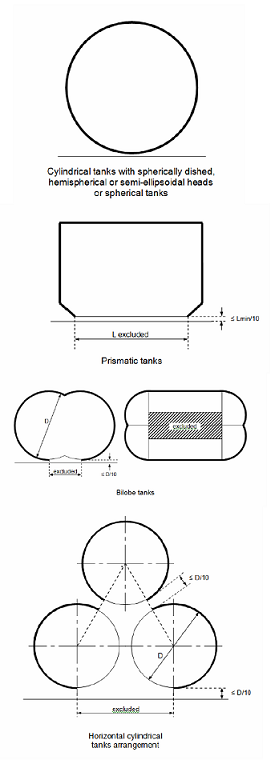
Figure 6.7.1
6.7.3.1.2 For vacuum insulated tanks in fuel storage hold spaces and for
tanks in fuel storage hold spaces separated from potential fire loads by coffer dams
or surrounded by ship spaces with no fire load the following applies:
- If the pressure relief valves have to be sized
for fire loads the fire factors according may be reduced to the following
values:
- F = 0.5 to F = 0.25
- F = 0.2 to F = 0.1
- The minimum fire factor is F = 0.1
6.7.3.1.3 The required mass flow of air at relieving conditions is given
by:
where density of air (ρair) = 1.293 kg/m3
(air at 273.15 K, 0.1013 MPa).
6.7.3.2 Sizing of vent pipe system
6.7.3.2.1 Pressure losses upstream and downstream of the PRVs, shall be
taken into account when determining their size to ensure the flow capacity required
by 6.7.3.1.
6.7.3.2.2 Upstream pressure losses
-
.1 the pressure drop in the vent line from the tank to the PRV
inlet shall not exceed 3% of the valve set pressure at the calculated flow
rate, in accordance with 6.7.3.1;
-
.2 pilot-operated PRVs shall be unaffected by inlet pipe
pressure losses when the pilot senses directly from the tank dome; and
-
.3 pressure losses in remotely sensed pilot lines shall be
considered for flowing type pilots.
6.7.3.2.3 Downstream pressure losses
-
.1 Where common vent headers and vent masts are fitted,
calculations shall include flow from all attached PRVs.
-
.2 The built-up back pressure in the vent piping from the PRV
outlet to the location of discharge to the atmosphere, and including any
vent pipe interconnections that join other tanks, shall not exceed the
following values:
- .1 for unbalanced PRVs: 10% of MARVS;
- .2 for balanced PRVs: 30% of MARVS; and
- .3 for pilot operated PRVs: 50% of
MARVS.
- Alternative values provided by the PRV
manufacturer may be accepted.
6.7.3.2.4 To ensure stable PRV operation, the blow-down shall not be less
than the sum of the inlet pressure loss and 0.02 MARVS at the rated capacity.
6.8 Regulations on loading limit for liquefied gas fuel tanks
6.8.1 Storage tanks for liquefied gas shall not be filled to more than a volume
equivalent to 98% full at the reference temperature as defined in 2.2.36.
A loading limit curve for actual fuel loading temperatures shall be prepared from the
following formula:
where:
- LL = loading limit as defined in 2.2.27, expressed in per cent;
- FL = filling limit as defined in 2.2.16 expressed in per cent, here
98%;
- ρR = relative density of fuel at the reference temperature;
and
- ρL = relative density of fuel at the loading temperature.
6.8.2 In cases where the tank insulation and tank location make the probability very
small for the tank contents to be heated up due to an external fire, special
considerations may be made to allow a higher loading limit than calculated using the
reference temperature, but never above 95%. This also applies in cases where a
second system for pressure maintenance is installed, (refer to 6.9). However, if the
pressure can only be maintained / controlled by fuel consumers, the loading limit as
calculated in 6.8.1 shall be used.
6.9 Regulations for the
maintaining of fuel storage condition
6.9.1 Control of tank pressure and temperature
6.9.1.1 With the exception of liquefied gas fuel tanks designed to
withstand the full gauge vapour pressure of the fuel under conditions of the upper
ambient design temperature, liquefied gas fuel tanks' pressure and temperature shall
be maintained at all times within their design range by means acceptable to the
Administration, e.g. by one of the following methods:
- .1 reliquefaction of vapours;
- .2 thermal oxidation of vapours;
- .3 pressure accumulation; or
- .4 liquefied gas fuel cooling.
The method chosen shall be capable of maintaining tank pressure below
the set pressure of the tank pressure relief valves for a period of 15 days assuming
full tank at normal service pressure and the ship in idle condition, i.e. only power
for domestic load is generated.
6.9.1.2 Venting of fuel vapour for control of the tank pressure is not
acceptable except in emergency situations.
6.9.2 Design of systems
6.9.2.1 For worldwide service, the upper ambient design temperature
shall be sea 32°C and air 45°C. For service in particularly hot or cold zones, these
design temperatures shall be increased or decreased, to the satisfaction of the
Administration.
6.9.2.2 The overall capacity of the system shall be such that it can
control the pressure within the design conditions without venting to atmosphere.
6.9.3 Reliquefaction systems
6.9.3.1 The reliquefaction system shall be designed and calculated
according to 6.9.3.2. The system has to be sized in a sufficient way also in case of
no or low consumption.
6.9.3.2 The reliquefaction system shall be arranged in one of the
following ways:
- .1 a direct system where evaporated fuel is compressed, condensed
and returned to the fuel tanks;
- .2 an indirect system where fuel or evaporated fuel is cooled or
condensed by refrigerant without being compressed;
- .3 a combined system where evaporated fuel is compressed and
condensed in a fuel/refrigerant heat exchanger and returned to the fuel tanks;
or
- .4 if the reliquefaction system produces a waste stream containing
methane during pressure control operations within the design conditions, these
waste gases shall, as far as reasonably practicable, be disposed of without
venting to atmosphere.
6.9.4 Thermal oxidation systems
6.9.4.1 Thermal oxidation can be done by either consumption of the vapours according
to the regulations for consumers described in this Code or in a dedicated gas
combustion unit (GCU). It shall be demonstrated that the capacity of the oxidation
system is sufficient to consume the required quantity of vapours. In this regard,
periods of slow steaming and/or no consumption from propulsion or other services of
the ship shall be considered.
6.9.5 Compatibility
6.9.5.1 Refrigerants or auxiliary agents used for refrigeration or cooling of fuel
shall be compatible with the fuel they may come in contact with (not causing any
hazardous reaction or excessively corrosive products). In addition, when several
refrigerants or agents are used, these shall be compatible with each other.
6.9.6 Availability of systems
6.9.6.1 The availability of the system and its supporting auxiliary services shall be
such that in case of a single failure (of mechanical non-static component or a
component of the control systems) the fuel tank pressure and temperature can be
maintained by another service/system.
6.9.6.2 Heat exchangers that are solely necessary for maintaining the pressure and
temperature of the fuel tanks within their design ranges shall have a standby heat
exchanger unless they have a capacity in excess of 25% of the largest required
capacity for pressure control and they can be repaired on board without external
sources.
6.10 Regulations on atmospheric control within the fuel containment
system
6.10.1 A piping system shall be arranged to enable each fuel tank to be
safely gas-freed, and to be safely filled with fuel from a gas-free condition. The
system shall be arranged to minimize the possibility of pockets of gas or air
remaining after changing the atmosphere.
6.10.2 The system shall be designed to eliminate the possibility of a flammable
mixture existing in the fuel tank during any part of the atmosphere change operation
by utilizing an inerting medium as an intermediate step.
6.10.3 Gas sampling points shall be provided for each fuel tank to monitor the
progress of atmosphere change.
6.10.4 Inert gas utilized for gas freeing of fuel tanks may be provided externally to
the ship.
6.11 Regulations on atmosphere control within fuel storage hold spaces (Fuel
containment systems other than type C independent tanks)
6.11.1 Interbarrier and fuel storage hold spaces associated with liquefied gas fuel
containment systems requiring full or partial secondary barriers shall be inerted
with a suitable dry inert gas and kept inerted with make-up gas provided by a
shipboard inert gas generation system, or by shipboard storage, which shall be
sufficient for normal consumption for at least 30 days. Shorter periods may be
considered by the Administration depending on the ship's service.
6.11.2 Alternatively, the spaces referred to in 6.11.1 requiring only a partial
secondary barrier may be filled with dry air provided that the ship maintains a
stored charge of inert gas or is fitted with an inert gas generation system
sufficient to inert the largest of these spaces, and provided that the configuration
of the spaces and the relevant vapour detection systems, together with the
capability of the inerting arrangements, ensures that any leakage from the liquefied
gas fuel tanks will be rapidly detected and inerting effected before a dangerous
condition can develop. Equipment for the provision of sufficient dry air of suitable
quality to satisfy the expected demand shall be provided.
6.12 Regulations on environmental control of spaces surrounding type C
independent tanks
6.12.1 Spaces surrounding liquefied gas fuel tanks shall be filled with suitable dry
air and be maintained in this condition with dry air provided by suitable air drying
equipment. This is only applicable for liquefied gas fuel tanks where condensation
and icing due to cold surfaces is an issue.
6.13 Regulations on inerting
6.13.1 Arrangements to prevent back-flow of fuel vapour into the inert gas system
shall be provided as specified below.
6.13.2 To prevent the return of flammable gas to any non-hazardous spaces, the inert
gas supply line shall be fitted with two shutoff valves in series with a venting
valve in between (double block and bleed valves). In addition, a closable non-return
valve shall be installed between the double block and bleed arrangement and the fuel
system. These valves shall be located outside non-hazardous spaces.
6.13.3 Where the connections to the fuel piping systems are non-permanent, two
non-return valves may be substituted for the valves required in 6.13.2.
6.13.4 The arrangements shall be such that each space being inerted can be isolated
and the necessary controls and relief valves, etc. shall be provided for controlling
pressure in these spaces.
6.13.5 Where insulation spaces are continually supplied with an inert gas as part of
a leak detection system, means shall be provided to monitor the quantity of gas
being supplied to individual spaces.
6.14 Regulations on inert gas
production and storage on board
6.14.1 The equipment shall be capable of producing inert gas with oxygen content at
no time greater than 5% by volume. A continuous-reading oxygen content meter shall
be fitted to the inert gas supply from the equipment and shall be fitted with an
alarm set at a maximum of 5% oxygen content by volume.
6.14.2 An inert gas system shall have pressure controls and monitoring arrangements
appropriate to the fuel containment system.
6.14.3 Where a nitrogen generator or nitrogen storage facilities are installed in a
separate compartment outside of the engine-room, the separate compartment shall be
fitted with an independent mechanical extraction ventilation system, providing a
minimum of 6 air changes per hour. A low oxygen alarm shall be fitted.
6.14.4 Nitrogen pipes shall only be led through well ventilated spaces. Nitrogen
pipes in enclosed spaces shall:
- - be fully welded;
- - have only a minimum of flange connections as needed for fitting of valves;
and
- - be as short as possible.